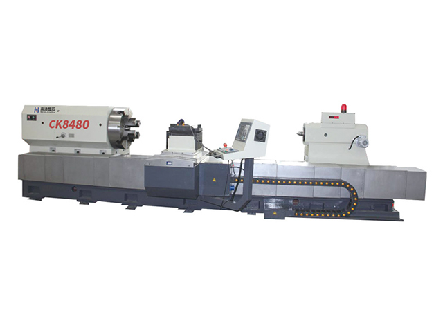
This machine tool is a dedicated machine tool for rolls, mainly used by steel mills to process the hole shapes of roll bodies. It uses special indexable tools to process and repair the hole shapes of various rolls with roll bodies ranging from Ф150 to Ф800mm. It can also perform rough machining on the outer cylindrical surface of the rolls and the processing of some other shaft parts.
Brief Introduction to the Main Structure of the machine tool
1 Bed
The bed has four guide rails. The headstock is installed at the left end of the bed, and the oil pool is set outside the bed for easy maintenance. The oil pool lubricates the headstock. The tool rest, tailstock and center rest are installed on the bed and can move longitudinally along its guide rails.
Between each guide rail of the bed, there are chip removal channels. Iron chips can be discharged to the ground at the back through the chip removal holes for removal.
2 Headstock
The headstock is a closed box, inside which all the main drive mechanisms from the main motor to the spindle are installed. The main motor is a spindle servo motor, featuring pure gear transmission with stepless speed regulation, enabling the spindle to achieve a rotational speed range of 2 to 240r/min.
The power of the main drive is transmitted to the headstock through a 30KW AC asynchronous motor via a pulley. All the drive shafts are installed on rolling bearings, and the main shaft is mounted on a high-precision double-row cylindrical roller bearing with adjustable radial clearance, which enables the main shaft to rotate smoothly and with high precision.
Behind the headstock, there is a device for lubricating all the transmission mechanisms, and the oil is supplied by a gear oil pump driven by a separate motor. To ensure that the lubrication conditions of the front and rear bearings of the main shaft are good, not only are separate oil pipes with sufficient oil quantity used for lubrication, but also a mercury switch type protection device is adopted to protect the oil quantity.
Three pallet boxes
The chute box is a closed box fixed below the front part of the large tool rest. It is equipped with a servo feed mechanism inside and is driven by a ball screw. The function of the chute box is to enable the tool rest to achieve various movements.
4 Knife rest
The tool rest of this machine tool is a cast steel integral tool rest. Its power is driven by the internal servo feed mechanism and ball screw transmission, which in turn drives the transverse slide plate to move laterally. A knife pad is installed at the front end of the cross slide plate for placing the knife tip.
5 Tail seat
The tailstock adopts an integral part. The upper body of the tailstock is equipped with a main shaft component and a sleeve moving mechanism, while the lower body of the tailstock is fitted with a rapid moving mechanism and a tailstock anti-reverse mechanism. The tailstock rapid movement mechanism is driven by the motor of the rear side reducer. Through a pair of spur gear pairs and worm gear pairs, it is transmitted to the final link - the rack and pinion pair, enabling the tailstock to move rapidly. The tailstock anti-retreat mechanism has a control handle at the tail end of the tailstock, which is used to control the semi-fish-tail-shaped anti-retreat claw. When fixing the tailstock, the control handle can insert the semi-fish-tail-shaped anti-retreat claw into the cast teeth on the side of the bed.

 QR Code